|
APPLICATION The wind tunnel is designed for calibration and testing dynamic response and impact of natural convection of low velocity thermal anemometers. It is a 'closed' wind tunnel with two measuring sections where tested probe is placed. The measuring sections, made of Plexiglas, have cross dimensions: 150x150mm and 75x75mm. The velocity range that can be achieved in the working section is respectively 0,03 to 3 m/s and 0,1 to 12 m/s. The wind tunnel is equipped with a measurement module and sucking fan that is controlled by an electronic module. The measurement module comprises barometric pressure and temperature units. A RS232 output enables computer control and calculation of flow velocity in the wind tunnel. |
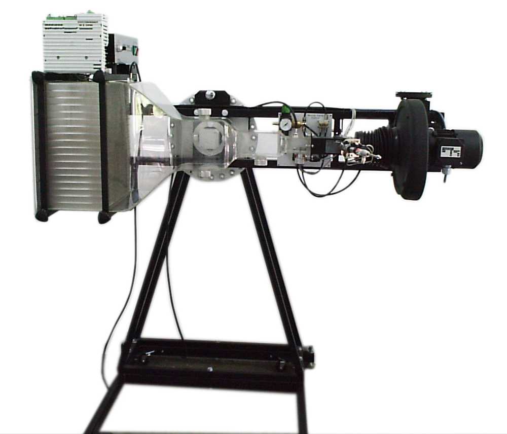 |
The tunnel allows static pressure to be measured in the two sections. It is used to calibrate the wind tunnel and to adjust the air velocity needed in the working section. Changing the rotational speed of an exhaust fan sucking air through the wind tunnel adjusts the air velocity in the working section.


A Laser Doppler Anemometer is used as a reference during the calibration of the wind tunnel. The calibration characteristic of the wind tunnel, i.e., the velocity in the wind tunnel as a function of the pressure difference between external sections and the air density, is approximated by a polynomial equation. Using a precise micromanometer, like Furness Control FCO510 that is equipped with RS232 output, enables the automatic control of the velocity in the wind tunnel.
|
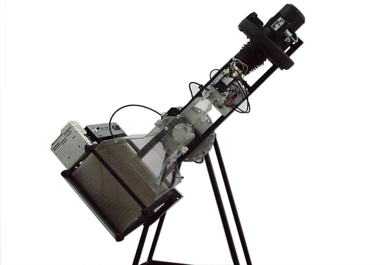
Optionally the wind tunnel can be equipped with
two systems. The first system allows for studying the impact of natural
convection on the accuracy of low velocity measurements (this effect
is different for the low velocity sensors available on the market today).
In this case a stand that allows for rotation of the whole wind tunnel
360° is provided. |
TECHNICAL DATA
repeatability of the calibration: better than ±0.008 m/s.
measurement of pressure difference in the range 0-1500Pa with a resolution
0.01Pa is required
velocity range: 0,03 to 3 m/s and 0,1 to 12 m/s.
airflow direction: 0-360O (optional)
sinusoidal fluctuations of flow velocity: 0.05 2 Hz (optional)